Work Summary, March to June 2023
 Haifei
A summary of the on-and-off work I have done from March this year until now
1 RTL-SDR & PYNQ-Z2
1.1 Current Work
This work connects an RTL-SDR to a PYNQ-Z2 over USB 2.0 so that the two can be used together. The RTL-SDR downconverts the RF signal to a baseband signal. The PYNQ-Z2 receives the baseband signal from the RTL-SDR through its USB 2.0 port and processes it with the FPGA. In the end, a simple FM radio web application can be built in a PYNQ Jupyter Notebook.
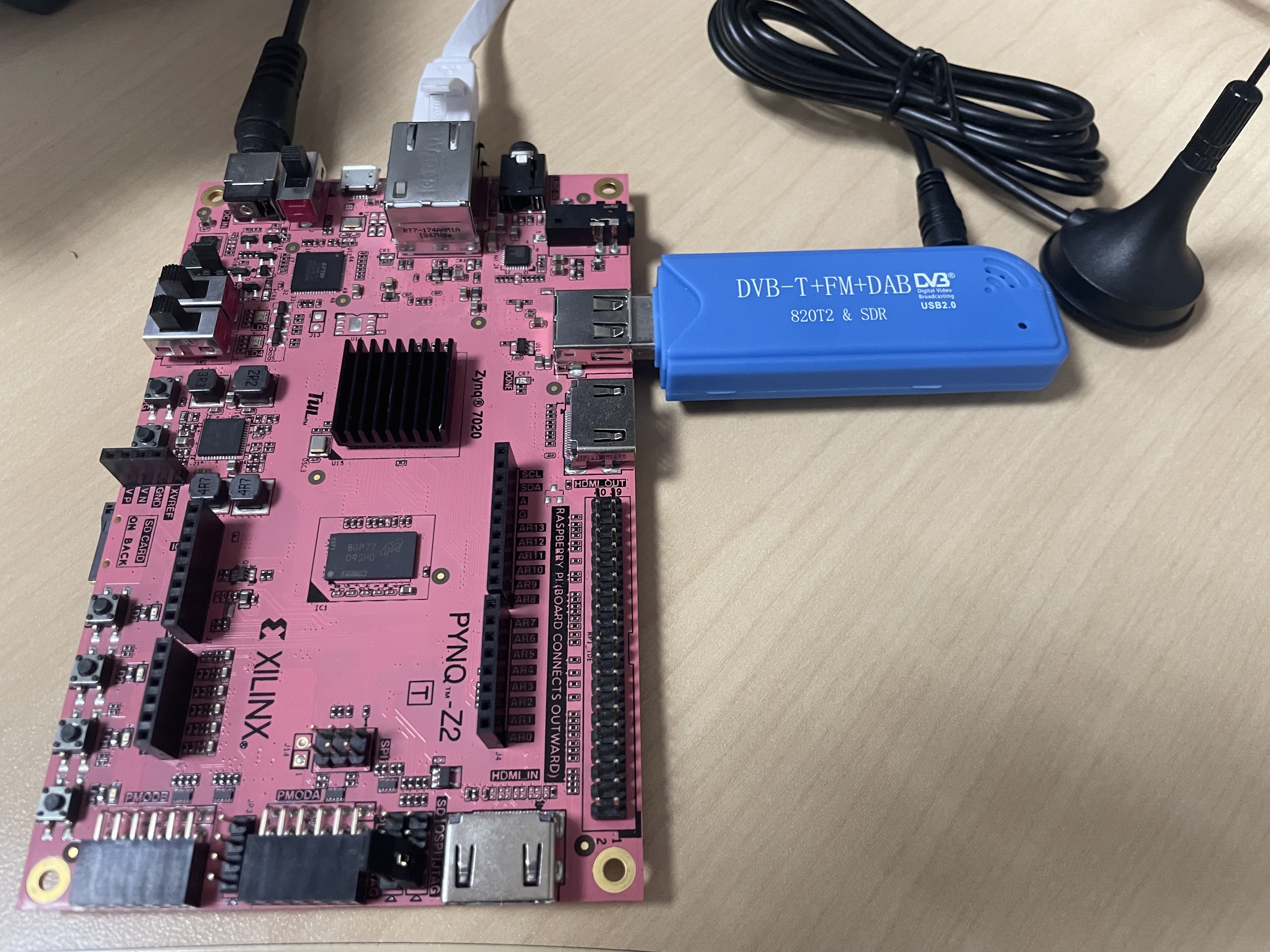
PYNQ-Z2 + RTL-SDR
For details, see
1.2 Possible Improvements
- Tuning with the slider widget in Jupyter Notebook is somewhat laggy. Offloading more of the CPU’s work to the FPGA would reduce the load on the CPU and therefore the lag.
2 AD9361 + PYNQ Kernel
2.1 Current Work
This work is basically to build the PYNQ and AD9361 drivers into the same kernel with Petalinux. MicroPhase in China has done this, but did not use the FPGA for data processing.
On the ZedBoard, the combination of 2019_R1 and PYNQ v2.4 works. Qixing and I summarized the build steps, the problems that may come up, and their solutions at this link.
On the PYNQ-ZU, the BSP exists only for PYNQ v2.7 and later. PYNQ v2.7 needs the 2020 toolchain, and that version ran into some problems (see Section 2.2.1), so this did not succeed.
2.2 Problems Encountered
2.2.1 ADI’s Yocto Layer Is Incompatible with PYNQ
In versions after 2019, the recipes-bsp of meta-adi overwrites the changes introduced by PYNQ’s recipes-bsp.
Below is part of the file meta-adi-xilinx/recipes-bsp/device-tree/device-tree.bbappend:
| |
It simply overwrites system-top.dts. A better practice would be to append code to system-top.dts (this is what PYNQ does).
For this reason, I did not manage to build a kernel with ADI master branch + PYNQ v3.0.1. It may be possible to modify recipes-bsp to make it compatible with PYNQ, but this work has been shelved. We also have a good reason to shelve it. See the next section (Section 2.2.2).
In addition, Yocto officially recommends that when several Yocto layers are used, one should check the OpenEmbedded Layer Index and the Yocto Project Compatible Index to see whether the layers are compatible with each other. Unfortunately, neither index includes meta-pynq or meta-adi.
2.2.2 The FPGA MANAGER Problem
The meta-adi-xilinx documentation states explicitly that they have no official support for FPGA MANAGER. If FPGA MANAGER is disabled, the bitstream cannot be reloaded after the board boots. PYNQ then loses its point.
My guess is that ADI treats the FPGA as a peripheral with a fixed function. That is, the device tree and the bitstream are both loaded at boot and are not meant to be changed. This fundamentally contradicts the idea of PYNQ.
Therefore, I do not recommend integrating the AD9361 and PYNQ drivers into one kernel. Instead, the AD9361 device tree and bitstream should be loaded dynamically after the system boots. See the next section (Section 3).
3 User-Space AD9361 Driver
3.1 Existing Work
To get around the difficulty described in the previous section, the AD9361 driver can run in user space and does not have to be integrated into the kernel. However, to talk to the SPI interface of the AD9361, a spidev node has to be added to the Linux device tree, so that SPI can be read and written through the file /dev/spidevx.y.
In
/dev/spidevx.y,xis the index of the SPI controller andyis the index of the chip select. With the PS SPI, the device name may be/dev/spidev0.0. With the PL SPI (AXI SPI), the device name may be/dev/spidev1.0.
The device tree is usually loaded by U-Boot at boot and cannot be modified afterwards. Since version 4.14, however, the Linux kernel supports the device tree overlay (DTO for short). A DTO allows a new device tree to be loaded dynamically at run time. The PYNQ library also provides an API for this:
| |
This API can download the bitstream (bitfile_name) and can also load a new device tree incrementally at run time (dtbo). Below is the device tree code that adds spidev through the AXI SPI:
| |
A few points to note:
- A line
/plugin/;has to be added after/dts-v1/;to mark the file as a Device Tree Overlay and not an ordinary Device Tree. ADI’s recipes-bsp decides whether a device tree is an overlay by checking whether the file contains/plugin/;.targetspecifies which node to modify. Here it is<&amba>, which expands to the phandle of the node labeledamba. For example, if the phandle of theambanode is70, then<&amba>actually stands for<70>. A phandle uniquely identifies a node and is usually assigned by the compiler (dtc).- The compile option
-@is usually needed. It enables symbols, so that device tree nodes can be referenced by label. Otherwise they can only be referenced by the absolute value of the phandle.
The DTO compiled from the file above works with the AXI SPI. This is the earlier work of Qixing and others. However, after the daughter card was changed from the V3 FMC9361_1.0 (datasheet, schematic) to the FMCOMMS2/FMCOMMS3, SPI communication ran into problems. See the next section (Section 3.2).
3.2 Problems Encountered
3.2.1 SPI Communication Problem
An AD9361 SPI command is two bytes long, in the following format:
D15 D14 D13 D12 D11 D10 D9:D0 W/R NB2 NB1 NB0 X X A[9:0] where
- W/R selects write or read (1 for write, 0 for read),
- NB2:NB0 is the number of bytes to read or write,
- A[9:0] is the register address. When sending (writing) data, the data follows the two-byte command. When receiving (reading) data, reading can start right after the command is sent.
The register at address
0x037of the AD9361 storesPRODUCT_ID. For AD9361 Rev 2,PRODUCT_IDshould be0x0A.When the AD9361 is initialized, the driver first performs a hardware reset through
GPIO_RESETB(at least 1 us), then reads register0x037and checksPRODUCT_ID.
After the V3 FMC9361_1.0 (V3 for short) was replaced with the FMCOMMS2 (S2 for short) and the FMCOMMS3 (S3 for short), and the pin constraints were updated, SPI communication failed.
S2 and S3 can almost be regarded as the same card. Their pin definitions are identical.
There is no public documentation for the V3 card online. This is why we wanted to move to ADI’s official FMCOMMS2/FMCOMMS3 evaluation boards.
Specifically, after the master (the AXI SPI controller) sends 0x037 on MOSI (read the register at address 0x037), the slave (the AD9361) does not send 0x0A (PRODUCT_ID) on MISO. What actually happens is shown below:
| Daughter card | Symptom | Waveform |
|---|---|---|
| V3 | MISO correctly returns 0x0A | 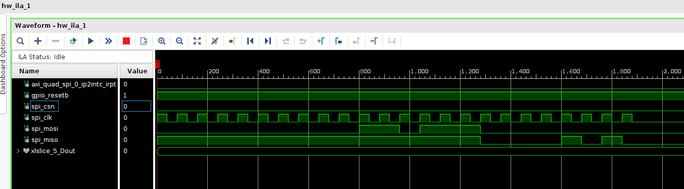 |
| S2 | MISO stays low, so 0x00 is read | 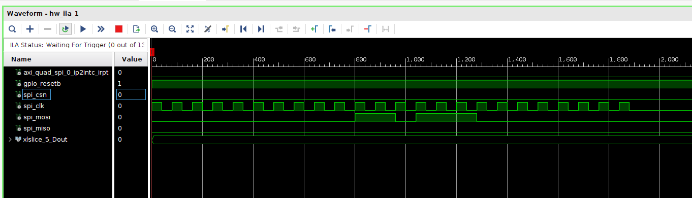 |
| S3 | MISO stays high, so 0xFF is read | 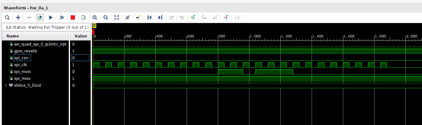 |
I tried both the Linux SPI driver and a bare-metal program. The symptom was the same.
The factors considered are as follows:
| Factor | Consideration |
|---|---|
| Pin constraints | Checked the pin constraints of MOSI, MISO, CS, and CLK of the 4-wire SPI against the schematic several times |
| Reset | Confirmed with the ILA that GPIO_RESETB was pulled low for 1 ms |
| SPI mode | Confirmed that the SPI mode is 0x01 (CPOL=0, CPHA=1) |
| SPI clock | The clock frequency of the AXI SPI is already set very low in the Block Design (the 10 ns system clock divided by 80). Clock quality can probably be ruled out. |
| I/O standard | Confirmed in the ZU schematic that VADJ is 1.8 V and VCCO is also 1.8 V, as required. |
| Driver | It is certainly not a software problem, because S2/S3 and V3 use the same driver. |
PYNQ-ZU + FMCOMMS2/3
| |
PYNQ-ZU + V3 (FMC9361_V1.0)
| |
ZCU104 + FMCOMMS2/3
| |
On the ZU + S2/S3 platform, SPI cannot read PRODUCT_ID.
The 104/102 + S2/S3 platforms can read PRODUCT_ID, however. This suggests that the problem is probably related to the FMC pins of the ZU itself.
The problem did not appear with the V3 daughter card because V3 and S2/S3 use different FMC pins for SPI.
Further testing may need an oscilloscope.
For now, the ZU board can be put aside in favor of the 104 + S2 platform for the later PYNQ + SDR applications.
3.2.2 *Device Tree Overlay Problem
Loading the Device Tree Overlay (*.dtbo) on the ZCU102/ZCU104 reports no error, but the /dev/spidev1.0 device does not appear.
Apart from the pin constraints and the part number, the Vivado projects for the ZCU102/104 are the same as that for the ZU, so the
pl.dtsigenerated from the xsa file is no different from the one for the ZU.
My preliminary guess is that the cause is related to the dtc compiler (I seem to have met a similar problem before, and it was caused by the dtc version).
| |
| |
The system.dtbo obtained by compiling the system.dtso file above with dtc -O dtb -o system.dtbo -b 0 -@ system.dtso works on the PYNQ-ZU. On the ZCU104, however, the /dev/spidev1.0 device cannot be found.
In addition, on both the PYNQ-ZU and the ZCU104, dmesg shows the following warnings:
| |
These warnings can apparently be ignored.
This problem has to be solved if the later PYNQ SDR applications are to be built on the 104 + S2 platform.
4 Summary
| Item | Result | Problem |
|---|---|---|
| Using the PYNQ-Z2 with an RTL-SDR | Built a small FM radio web app based on Jupyter Notebook | Performance can still be improved |
| Integrating the AD9361 driver into the PYNQ kernel | PYNQ v2.4 + meta-adi 2019_R1 works | In versions after 2019, meta-adi does not support FPGA_MANAGER |
| Driving the AD9361 from user space | Works on the V3 daughter card. The hardware integrates FFT and FIR IP cores for data processing | On the ZU + S2/S3 platform, SPI cannot read PRODUCT_ID. The 104/102 + S2/S3 platforms can read it, however, which suggests that the problem is probably related to the FMC pins of the ZU itself. The problem did not appear with the V3 daughter card because V3 and S2/S3 use different FMC pins for SPI. Further testing may need an oscilloscope. For now, the ZU board can be put aside in favor of the 104 + S2 platform for the later PYNQ + SDR applications. |