Reaching 1 K with a Helium Sorption Refrigerator
 Haifei
People who meet a superconducting nanowire single-photon detector (SNSPD) system for the first time often notice something that looks contradictory. The lab has only a helium compressor and a small vacuum chamber. There is no liquid helium dewar and none of the elaborate equipment of a dilution refrigerator. Yet the monitoring software shows a temperature as low as 0.85 K.
The puzzle is this. A GM cryocooler, made of a compressor and a cold head, can usually cool its cold stage only to about 2.8 K. So what carries the system from 2.8 K down to 0.85 K?
The last step is done by a helium sorption pump inside the vacuum chamber. It has no moving parts. One automatic recycle a day is enough to keep the detector below 1 K. This article explains how the device works and how it runs in a real system.
1. Why SNSPDs Need Low Temperatures
The core of an SNSPD is a superconducting nanowire only a few nanometers thick and a little over a hundred nanometers wide. In operation, a DC bias current slightly below the critical current flows through the nanowire. A photon at 1550 nm carries only about 0.8 eV. When the nanowire absorbs it, this is still enough to break superconductivity locally, and a short section briefly becomes resistive. The readout circuit then sees a voltage pulse, which means a photon has been detected. After a few nanoseconds the nanowire is superconducting again and waits for the next photon.
A note here. How an absorbed photon destroys superconductivity step by step is still not fully settled. The hotspot model and vortex-assisted mechanisms each explain part of the experimental observations, and the debate continues. This does not stop us from understanding the SNSPD at the level of devices and engineering.
In practical performance, the SNSPD is the best single-photon detector available today overall. Commercial products above 90% system detection efficiency are common. The timing jitter can be a few picoseconds, and the dark count can be below one per second. This is why experiments that count photons one by one, such as quantum communication and deep-space laser communication, use this detector. Device physics is not the focus of this article. Interested readers can refer to the review by Natarajan et al. (Reference 4).
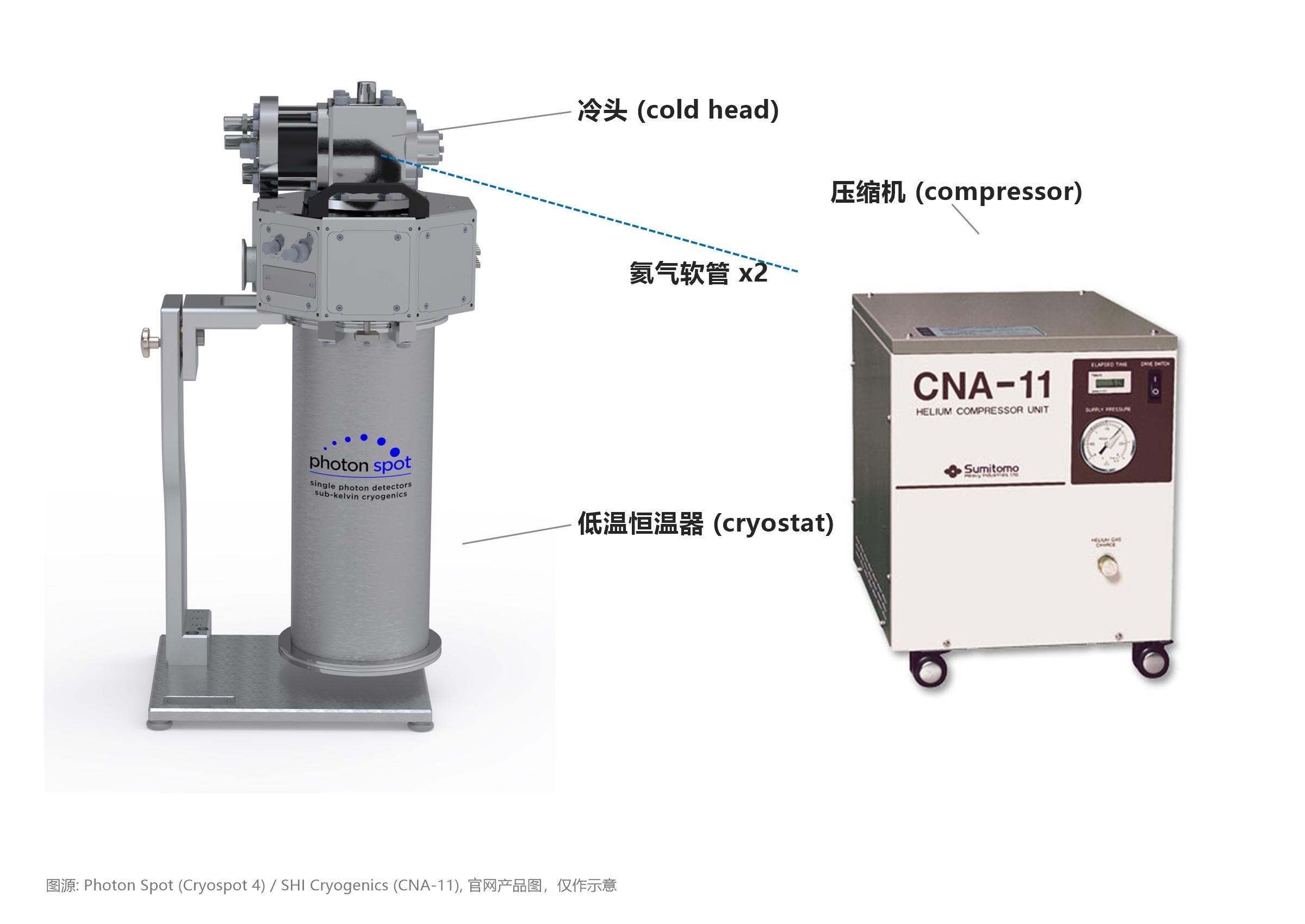
Figure 1. The three main pieces of hardware in an SNSPD system. On the left is the cryostat (the vacuum chamber in the text) with the GM cold head on top. On the right is the helium compressor. Two helium hoses connect them. Images from the product pages of Photon Spot (Cryospot 4) and SHI Cryogenics (CNA-11), for illustration only.
The price of this performance is low temperature. Every superconducting material has its own critical temperature (Tc below). A device has to operate far below Tc to obtain a high enough critical current and to keep the dark count down. As a rule of thumb, the operating temperature is usually below half of Tc. In other words, the cooling temperature is not a side specification. It directly sets how well the detector can perform.
How cold it has to be depends on the material of the nanowire. Polycrystalline NbN and NbTiN films have a Tc of about 8 to 10 K and already work well just above 2 K. Quite a few results show system efficiency above 90% at 2.1 K. Amorphous WSi and MoSi films have a Tc of only 3 to 5 K. To get the most out of these materials, the temperature has to go below 1 K. The 98% system detection efficiency record for MoSi was obtained at 0.7 K.
So the device problem turns into a refrigeration problem. Cooling a system from room temperature to 2.8 K is a mature technology. How do we then get below 1 K?
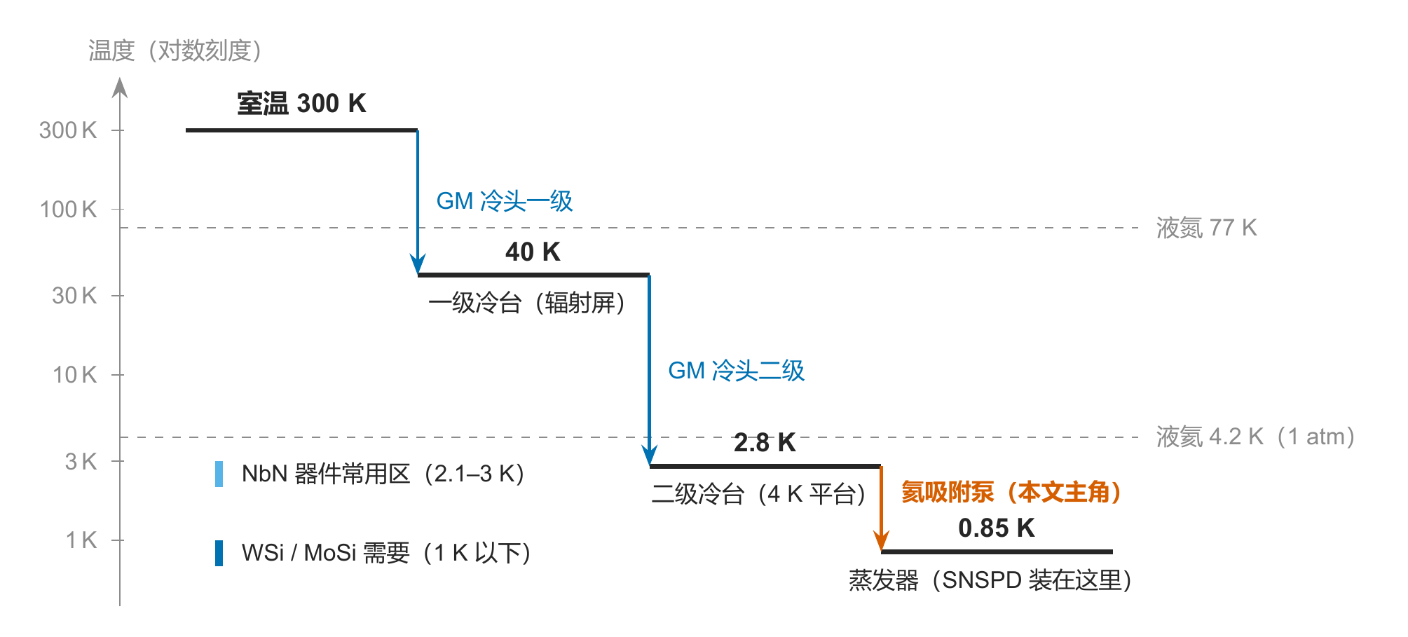
Figure 2. A three-leg relay from 300 K to 0.85 K. The vertical axis is logarithmic.
2. The First Leg, a Compressor and a GM Cold Head
In SNSPD systems, the step from room temperature to 2.8 K is usually done by a GM cryocooler (Gifford–McMahon cryocooler). A common configuration is the CNA-11 compressor from Sumitomo Heavy Industries (SHI) with the RDK-101D cold head. The CNA-11 is air-cooled. Some older systems use water-cooled compressors such as the HC-4E. Both cool in the same way. The main difference is whether the heat produced by the compressor goes into the air or into cooling water.
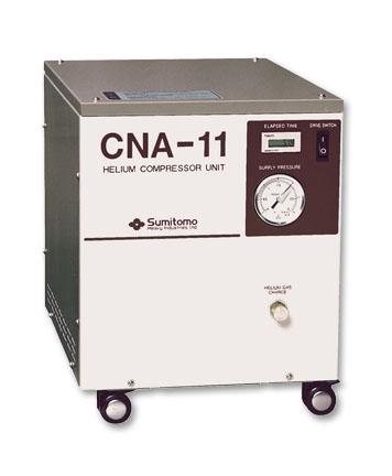
Figure 3. The CNA-11 air-cooled helium compressor. Image from the SHI Cryogenics Group website, for product illustration only.
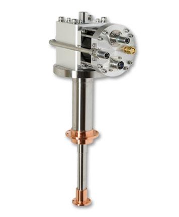
Figure 4. The RDK-101D two-stage GM cold head. Image from the SHI Cryogenics Group website, for product illustration only.
The compressor sits at room temperature. It compresses helium gas to about 20 atmospheres and sends it through two hoses to the cold head on top of the vacuum chamber. Inside the cold head is a displacer that moves back and forth. It is filled with a heat-storage material, and this part is called the regenerator. High-pressure helium entering the cold head first passes through the regenerator and is precooled. It then expands at the cold end, absorbs heat, and carries the heat back to the compressor. The process repeats about once or twice per second.
The RDK-101D has two cooling stages. The first stage sits at 40 to 60 K. It mainly cools the radiation shield, which blocks thermal radiation from the room-temperature surroundings. The second stage is what people in the lab call the “4 K stage”. With the CNA-11, its rated cooling power is 0.1 W @ 4.2 K. Cooling from room temperature to 4.2 K usually takes about two and a half hours. The lowest temperature without load is generally 2.6 to 3 K, and the exact value varies with the model and the heat load. The whole system draws about 1.2 to 1.5 kW, about the same as an electric kettle, and runs from an ordinary wall socket.
Why can’t the same method take us on to 1 K? The main limit is the regenerator. The regenerator material has to absorb and release heat in every cycle, but the specific heat of common materials drops sharply below 4 K. With too little specific heat, the regenerator cannot store enough heat within one cycle, and the cooling efficiency falls. In practice, replacing lead with rare-earth compounds such as HoCu₂ and Er₃Ni pushes the lower limit of a GM cryocooler from about 10 K to around 2 K. Further down, better regenerator materials are no longer enough. We need a different way to cool.
3. Pumping on Liquid Helium
The method used here is evaporative cooling. The effect is familiar. You feel cool after sweating, and alcohol on the skin cools it quickly. In both cases part of the liquid evaporates and takes latent heat with it. A molecule needs energy from the remaining liquid to leave the surface and enter the gas phase, so evaporation makes the liquid that is left behind colder.
The boiling point of a liquid depends on the pressure above its surface. This is also why water boils below 100 °C on a high plateau. At 1 atmosphere, liquid helium boils at 4.2 K. If we keep pumping away the helium vapor above the surface and bring the pressure down to 24 kPa, liquid helium boils at 3.0 K. Lower the pressure to 16 Pa, and the boiling point drops to 1.0 K. In other words, as long as the pump keeps removing the vapor, liquid helium cools itself while it evaporates.
This cannot go on all the way to 0 K. The saturated vapor pressure of liquid helium falls exponentially with temperature. At 1.0 K it is still about 16 Pa. At 0.85 K only two or three pascals remain. At lower temperatures there are fewer and fewer helium molecules above the surface to pump away, and even a faster pump cannot carry off much heat.
In addition, liquid helium becomes a superfluid below 2.17 K. Superfluid helium forms a very thin film along the container wall. The film creeps toward warmer places and evaporates there. This film creep brings extra heat to the cold end. The falling vapor pressure and film creep together limit single-stage ⁴He evaporative cooling. The lowest usable temperature is usually 0.8 to 1 K. With the rarer ³He in place of ⁴He, the same principle reaches about 0.3 K. This article does not go into that.
For SNSPDs, 0.85 K is already low enough, but building the system raises another problem. The traditional approach puts a mechanical vacuum pump at room temperature and runs a pumping line into the cold region to remove the helium vapor. Gas at low pressure flows poorly through a pipe, so the line has to be very wide. A wide line lets in more heat from the room-temperature end. It also carries the vibration of the mechanical pump into the cryogenic system. This is not convenient in practice.
A natural idea is to put the pump inside the 2.8 K vacuum chamber, right next to the liquid helium. This can be done. We replace the mechanical pump with a sorption pump that has no moving parts at all.
4. A Vacuum Pump with No Power Cord
The core material of a sorption pump is activated charcoal. Activated charcoal is full of pores a few nanometers across, so its specific surface area is very large, on the order of 1000 m²/g. Spread flat, the internal surfaces of one gram of activated charcoal would cover more than two basketball courts.
A helium atom that hits these surfaces is held there by van der Waals forces. This is called physisorption. Whether the atom stays depends on whether its thermal motion is enough to break free. For helium, adsorption becomes very strong below about 10 K. A small can with a few tens of grams of activated charcoal can then adsorb all the helium in a sealed gas circuit. Seen from the gas circuit, it is a vacuum pump with a very high pumping speed.
Conversely, heating the charcoal to 40 to 50 K releases the adsorbed helium. This is called desorption. So the same can of charcoal pumps gas when it is cold and gives the helium back when it is warmer. Switching between the two only takes a heater. There are no pistons, impellers, or other mechanical parts.
The whole sorption refrigerator is filled with helium and sealed at the factory. The helium circulates only inside the device, in a closed cycle. In normal operation the device neither consumes helium nor leaks it. Pumping on the liquid helium with such a sorption pump avoids the problems of a room-temperature mechanical pump and a wide pumping line.
5. What a Sorption Refrigerator Looks Like
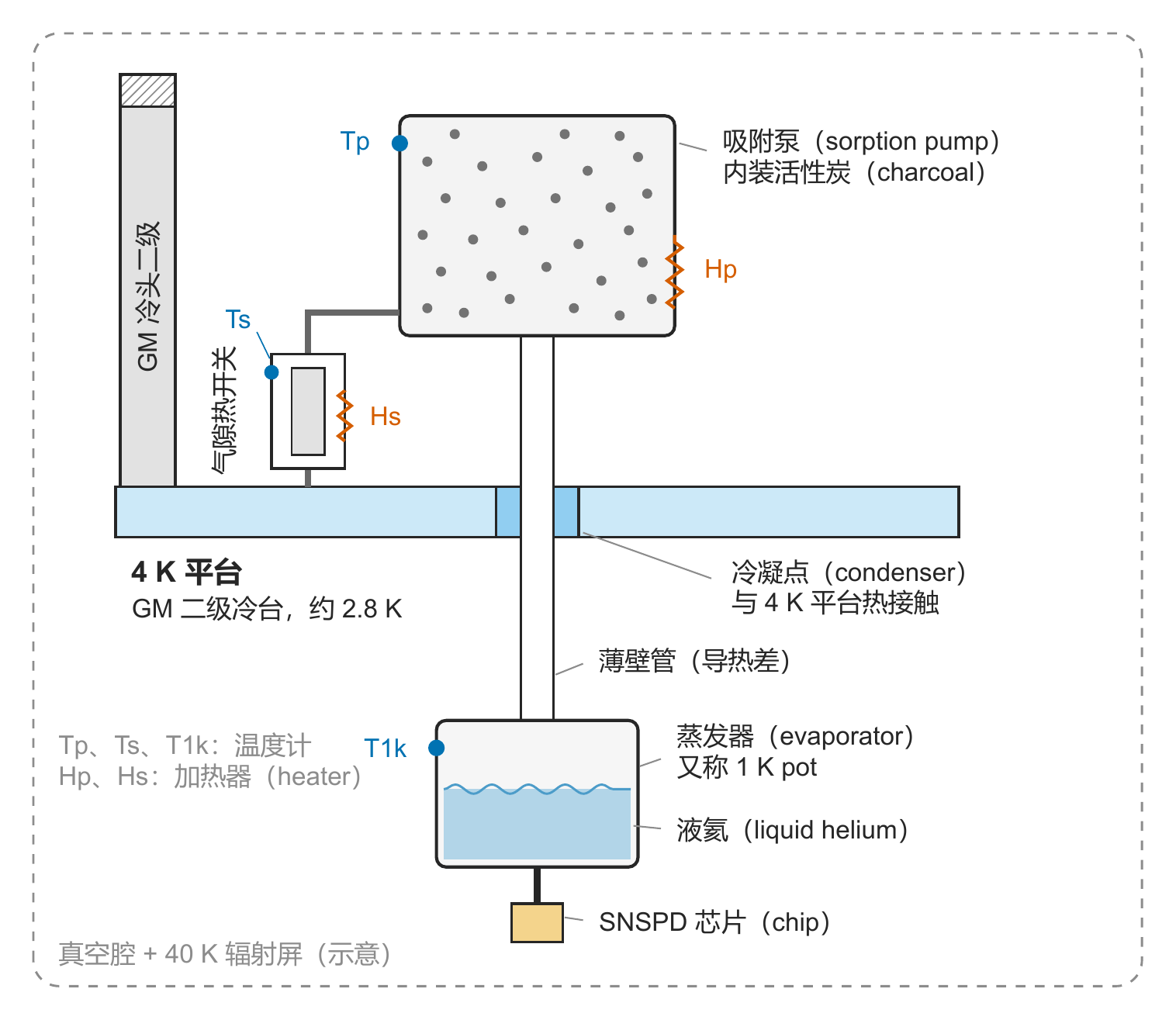
Figure 5. Structure of a ⁴He sorption refrigerator (drawn by the author).
The whole sorption refrigerator is a sealed insert mounted below the 4 K stage of the GM cold head. From top to bottom in Figure 5, it has four main parts.
- Sorption pump. This is the charcoal can described above, with a heater Hp and a thermometer Tp. Hp decides whether the charcoal adsorbs or desorbs. Tp is used to monitor and control the pump temperature.
- Gas-gap heat switch. It connects the sorption pump to the 4 K stage and controls the thermal contact between them. The switch is made of two nested metal cylinders with a very narrow gap between them. If the gap is under vacuum, almost no heat flows between the cylinders, and the switch is open. If the gap holds a little helium gas, heat flows through the gas, and the switch is closed. The helium in the gap is controlled by another small packet of activated charcoal. Powering the heater Hs of this packet makes it release helium, and the switch conducts. When the heating stops, the charcoal cools and adsorbs the helium again. The gap returns to vacuum and the switch opens. That is, the heat switch also works by adsorption and desorption, only on a smaller scale. Its thermal conductance when closed and when open can differ by three orders of magnitude, and again there is no mechanical motion.
- Condenser. This is a short section of the line thermally anchored to the 4 K stage. Helium gas passing through it is cooled to the stage temperature, and it condenses into liquid when the conditions are right.
- Evaporator. This is the small pot at the bottom that holds the liquid helium, often called the 1 K pot. The SNSPD chip can be mounted directly on the evaporator or connected to it through a cold finger. Thin-walled stainless steel tubes connect the evaporator to the parts above. Stainless steel conducts heat poorly, which keeps the 0.85 K evaporator as isolated as possible from the 2.8 K stage.
The three thermometers Tp, Ts, T1k and the two heaters Hp, Hs in the figure are the entire control interface of the refrigerator. Once these five quantities are clear, the condensation and evaporation cycle below is easy to follow.
6. Condense, Then Evaporate
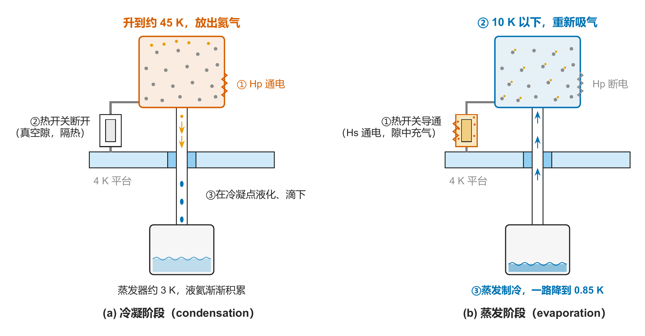
Figure 6. The two stages of the cycle (drawn by the author).
One recycle has two stages, condensation and evaporation. The condensation stage collects the helium in the line as a liquid. The evaporation stage then lowers the pressure above the liquid and cools it below 1 K.
The first step is condensation. The heat switch stays open, that is, Hs is not powered. The pump heater Hp is turned on, and a proportional-integral-derivative (PID) feedback loop holds Tp at about 45 K. As the charcoal warms, it starts to desorb. The adsorbed helium enters the sealed line, and the pressure in the line rises to a few tens of kPa.
When the line pressure exceeds the saturated vapor pressure at the stage temperature, helium gas condenses as it passes the condenser. For example, the saturated vapor pressure of liquid helium at 3.0 K is about 24 kPa. The GM cold head removes the latent heat released by condensation, and the droplets run down the line into the evaporator. After about forty minutes, most of the helium in the line has collected in the evaporator, which is now at about 3 K.
The second step is evaporation. Hp is switched off and Hs is turned on, so the gas-gap heat switch conducts. At first glance this looks backwards. We want to cool the sorption pump, yet the heater we turn on belongs to the heat switch. The reason is that heating Hs releases helium gas, which lets the heat switch conduct again. It is the 4 K stage that actually cools the sorption pump.
Once the heat switch conducts, Tp falls gradually from 45 K. When the pump drops below 10 K, the charcoal adsorbs strongly again and starts pumping away the helium vapor above the liquid in the evaporator. As the vapor pressure falls, the boiling point of the liquid helium falls with it, and continued evaporation carries away latent heat. In ten-odd minutes, T1k drops from about 3 K to around 0.85 K.
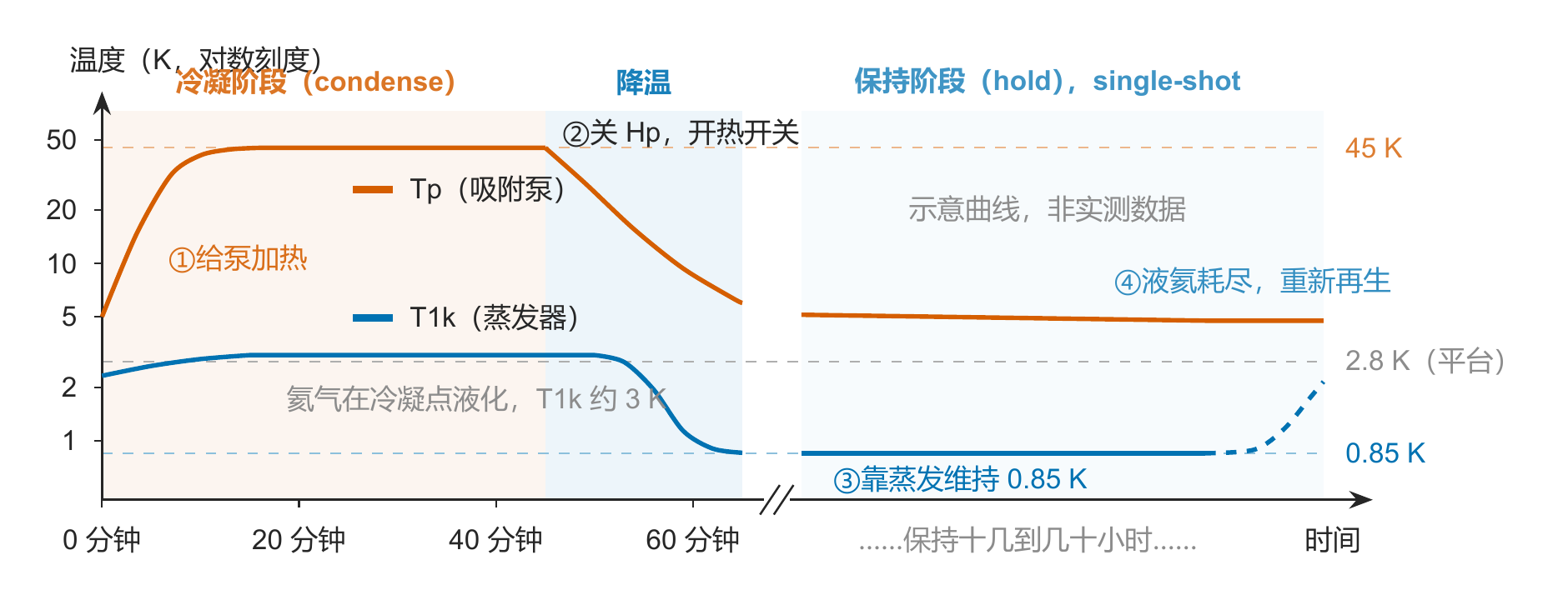
Figure 7. Pump temperature Tp and evaporator temperature T1k during one recycle (drawn by the author, not measured data).
The system then enters the hold stage. The sorption pump keeps pumping away helium vapor and holds T1k at about 0.85 K, while the liquid helium in the evaporator slowly runs down. How long this lasts depends mainly on the amount of liquid helium and the heat leaking in from outside.
We can make an order-of-magnitude estimate. The latent heat of vaporization of liquid helium is about 20 J/g, less than one percent of that of water. A cryogenic design therefore has to keep the total heat leak at the microwatt level. Suppose one condensation yields 1 g of liquid helium, about 7 mL, and the total heat leak into the evaporator is 100 μW. The theoretical hold time is then 20 J ÷ 100 μW ≈ 2.3 days. Real systems hold for anything from a dozen hours to a few days. This is usually enough for a full day of experiments.
When the liquid helium is used up, T1k rises noticeably. Running the condensation and evaporation steps again brings the system back to 0.85 K in about an hour. This mode of operation is called single-shot. After each recycle the system runs for a while, and when the liquid helium is gone it has to be recycled again. For most experiments, as long as this happens automatically once a day, it feels little different from continuous operation.
7. Running It Automatically with a CTC100
Looking back at the cycle, the control system really has only two jobs. It reads temperatures, and it sets heater power. A cryogenic temperature controller does exactly this.
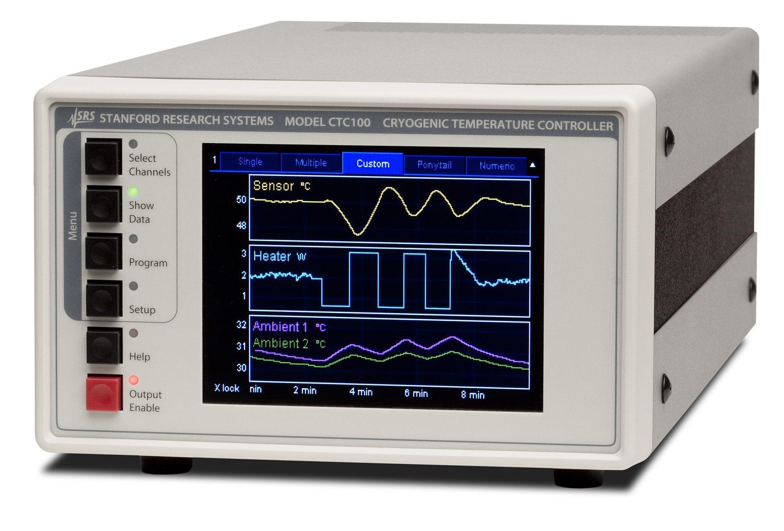
Figure 8. The CTC100 cryogenic temperature controller. Image from the Stanford Research Systems website, for product illustration only.
A common choice in SNSPD systems is the CTC100 from SRS (Stanford Research Systems) in the US. It has 4 sensor inputs and can read Tp, Ts, T1k, and the 4 K stage at the same time. Its two heater outputs give up to 100 W each, which is plenty for Hp and Hs. The CTC100 also has PID feedback and supports user macros, so the whole recycle procedure can be written as a script that is stored and run in the controller.
A typical recycle macro can go like this. At four in the morning, the controller first checks that the heat switch is open. It then turns on Hp and holds Tp at 45 K with PID. It waits about forty minutes so that the desorbed helium fully condenses in the evaporator. Next it switches off Hp and turns on Hs to close the heat switch. The controller keeps watching T1k and ends the recycle once T1k is below 0.9 K. By the time people arrive at the lab in the morning, the system is usually already stable at 0.85 K. For the macro language itself, see the CTC100 manual. This article does not go into it.
8. Conclusion
Now we can answer the question from the beginning. The compressor and the GM cold head cool the system from 300 K to about 2.8 K. The helium sorption refrigerator then takes the evaporator down to 0.85 K.
The whole system can be seen as three cooling legs. The first stage of the GM cold head cools the radiation shield at about 40 K. The second stage provides the cold stage at about 2.8 K. On that stage, helium is first condensed into a liquid. A cold charcoal sorption pump then keeps pumping away the vapor, and evaporative cooling takes the liquid below 1 K. Nothing moves in the cold region, and the helium circulates inside a sealed device. In daily use, the temperature controller only has to run an automatic recycle at regular intervals.
For NbN devices, the 2.8 K stage is often enough already. Materials with a lower critical temperature, such as WSi and MoSi, need the sub-1 K environment that a sorption refrigerator provides, and their record efficiencies were obtained in this temperature range.
To go colder, replacing ⁴He with ³He lets a single-stage sorption refrigerator reach about 0.3 K. Below that is the territory of the dilution refrigerator, which can reach about 10 mK. That is a different refrigeration principle altogether.
References
- RDK-101D(L) 4K Cryocooler Series, SHI Cryogenics Group website, https://shicryogenics.com/product/rdk-101dl-4k-cryocooler-series/
- CNA-11 Indoor Air-Cooled Compressor Series, SHI Cryogenics Group website, https://shicryogenics.com/product/cna-11-indoor-air-cooled-compressor-series-2/
- CTC100 Cryogenic Temperature Controller, Stanford Research Systems website, https://www.thinksrs.com/products/ctc100.html
- C. M. Natarajan, M. G. Tanner, and R. H. Hadfield, “Superconducting nanowire single-photon detectors: physics and applications,” Supercond. Sci. Technol. 25, 063001 (2012). (A review of SNSPDs)
- D. V. Reddy et al., “Superconducting nanowire single-photon detectors with 98% system detection efficiency at 1550 nm,” Optica 7, 1649 (2020). (The MoSi efficiency record at 0.7 K)
- W. Zhang et al., “NbN superconducting nanowire single photon detector with efficiency over 90% at 1550 nm wavelength operational at compact cryocooler temperature,” Sci. China Phys. Mech. Astron. 60, 120314 (2017). (High-efficiency NbN at 2.1 K)
- R. J. Donnelly and C. F. Barenghi, “The observed properties of liquid helium at the saturated vapor pressure,” J. Phys. Chem. Ref. Data 27, 1217 (1998). (Properties of liquid helium such as its vapor pressure)
- Chase Research Cryogenics website, https://www.chasecryogenics.com (A maker of commercial sorption refrigerators)
Figures 2, 5, 6, and 7 were drawn by the author. Figures 1, 3, 4, and 8 are from the manufacturers’ websites and are for product illustration only.
This article was written with the help of Claude Fable 5, using about 305.3k tokens.